SOLUTION BRIEF
How to Prevent Feedback and Damage in Ultrafast Fiber Lasers using Coherent Optical Isolators
1 The Effect of Feedback on Femtosecond Fiber Laser Systems
A little (optical) feedback can go a long way . . .
Rare-earth doped optical fiber has become a more widespread medium for ultrafast laser systems in both fiber-only and hybrid (fiber and bulk) lasers. However, there are design issues inherent to fiber-based oscillators and amplifiers. Because fiber is a high gain medium, any light that is inadvertently injected into the ultrafast oscillator, as well as into amplifiers, can degrade and potentially irreversibly affect system performance by causing instability (at best) or damage (at worst). Optical feedback is caused by back-reflections off of downstream optics or by amplified spontaneous emission (ASE) from amplifier stages, and it is amplified by the high gain in doped optical fibers. Small signal, single-pass gains of ~ 20 dB or more are typical in optical fibers, as opposed to the relatively lower gain of ~ 5 dB in bulk doped materials. The relatively smaller size of the beam at the end of a fiber, compared to bulk gain material, leads to higher intensity at the end face, and creates scenarios where fiber systems can reach the damage threshold at lower optical powers.
Glass fiber host laser media are “high gain”
- Geometry allows for more gain in a single pass than in bulk systems
- Gain can be up to 100x or more
- For Oscillators, output coupler can be ~ 70% or more
Generating pulses below 10 picoseconds (ps) and into the femtosecond (fs) range, ultrafast laser systems can be designed for a range of operating regimes, depending upon target pulse energies and repetition rates. Two typical configurations are 1) an optical Master Oscillator Power Amplifier (MOPA) scheme for ps pulses and often with hybrid bulk-fiber design, and 2) a Chirped Pulse Amplifier (CPA) scheme for fs pulses. Examples of these designs can be seen in Figures 1 and 2.
Practically speaking, whenever a laser system is designed using a mode-locked fiber oscillator as the pulse source, the oscillator typically provides only mW level output while system requirements can go to the 10s of Watts and beyond. Amplifiers are required to achieve performance targets, and often use large-mode area (LMA) amplifiers producing 1W to even up to more than 100W. But the oscillator can only remain stable with feedback on the microwatt (μW) level or less. Otherwise, noise that disturbs the spectral content can inhibit mode-locking or even cause Q-switching– the power that is fed back must be smaller than the ASE that pulses build from; this often means that an oscillator requires << 60 dB of feedback to remain stably mode-locked. In contrast, solid-state mode-locked oscillators can still operate with many times that amount of feedback. At the same time, if the seed pulse from the oscillator is interrupted at the input of an amplifier, Q-switching can result, which invariably leads to optical damage on a fiber end face.
A mechanism to prevent feedback from entering ultrafast fiber oscillators, and to protect the subsequent chain of amplifiers, is essential.
Fortunately, there is a solution to the problems arising from optical feedback the use of Coherent Optical Isolators.
2 Using a Faraday Isolator to Protect against Feedback
A Faraday Isolator is an optical device that provides high transmission of signal light in the forward direction, but strongly blocks light from the reverse direction. The main component in an optical isolator is the Faraday Rotator, which is made of a magneto-optic material with special properties; the Faraday Rotator operates by rotating the plane of polarized light 45 degrees in the forward direction and an additional 45 degrees of non-reciprocal rotation in the reverse direction, while maintaining the light’s linear polarization. When placed between crossed polarizers, a Faraday Rotator becomes a Faraday isolator. A Faraday Isolator protects laser oscillators and laser amplifiers from the deleterious effects of back reflections. Containing low absorption, high damage threshold optics, our Faraday Rotators and Isolators are ideally suited for use with average power levels of up to 50W for ultrafast laser systems.
When selecting an isolator, there are several criteria to keep in mind: the incident beam size, the incident optical power on the isolator, the required transmitted power for the next stage, and the amount of isolation required.
Find the Coherent Faraday Isolator that’s best suited for your requirements or shop online now.

Figure 1: Typical MOPA Design, showing the use of isolators (denoted ISO) and their locations in the beam path.

Figure 2: Typical CPA Design, showing the use of isolators (denoted ISO) and their locations in the beam path.
3 Installing a Faraday Isolator
Installing a Faraday Isolator in the optical path of a fiber laser system is relatively straight forward. Each Coherent Isolator comes with a User’s Manuali, which describes how to align the device in the beam path. The parameters of optical beam size, optical power and center wavelength and bandwidth must be taken into account when selecting the appropriate isolator as each are made to the exacting specifications of the selected model.
See Figures 1 and 2 for examples of where to install isolators in MOPA and CPA systems. An example of a real-world application can be found in reference 2ii.
4 Considerations Related to Dispersion
Dispersion is a significant issue for ultrafast lasers, one that can affect the pulse duration and therefore, the peak power, of ultrashort pulses. Dispersion occurs when light pulses travel in a medium where the phase velocity depends on its frequency (or wavelength). The Faraday material used to make an optical isolator is dispersive, and therefore pulses traversing through an isolator can broaden in length, although the magnitude and relevance of that effect depends on both the initial pulse and the application.
Generally, fiber laser systems produce pulses on the order of 100 fs or longer, with an optical bandwidth in the range of 10 - 30 nm or more. The actual system bandwidth, along with the length of the Faraday Rotator used in the isolator, will dictate the amount of pulse broadening that will occur. The amount of dispersion typically will not cause enough pulse distortion to negatively impact applications.
However, it is important to note that for pulses < 100 fs (pulses with broader bandwidth), the amount of dispersion will be greater - and this becomes an important consideration in many applications. As an example, in nonlinearly broadened systems, including certain CPA systems, it is possible to produce < 100 fs pulses. If an isolator is required at the output of the laser system due to the possibility of feedback from the laser application, such as in material processing, this will add to the overall group velocity dispersion budget. In some cases, the effects of dispersion caused by the output isolator can be mitigated or removed by balancing it with dispersion in other parts of the system.
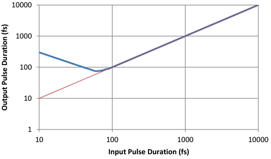
An example of how a Faraday Isolator using 8 mm of TGG can affect the pulse duration of ~ 1050 nm ultrashort pulses over the range from 10 – 10,000 fs, is shown in Figure 3. The graph was generated by determining how much group velocity dispersion (GVD) occurs for 1050 nm pulses. This was done using the Sellmeier Equation for TGGiii.

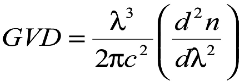
The group velocity dispersion (GVD), which introduces a frequency dependent delay to the different spectral components of the pulse (typically in units of fs2/m) is expressed asiv:

Solving analytically for the 2nd derivative of the refractive index, it is possible to calculate GVD and then the actual second order dispersion for a specific device (here denoted as β2, the second-order group delay dispersion), related to GVD by multiplying GVD by the length of the material – in this case, the TGG used in the isolator. This information can in turn be used to calculate the output pulse duration for given input pulse duration, after traveling through the length of TGG isolator material. For the case where the input pulse length squared, t0 2 , is much less than β2, an equation to express the pulse broadening proportional to β2 can be usedv.
By performing these calculations, the amount of dispersion, β2, over the range of 1030 - 1080 nm was found to be ~ 1100 fs2 for 8 mm long TGG. The estimated broadening from that amount of second order dispersion for pulses in the range of 10 – 10,000 fs is shown in the graph below.

Figure 3: Broadening of a femtosecond pulse at ~ 1050 nm after propagation through 8 mm of TGG (blue curve); the red curve shows the output for undistorted pulses.
5 Conclusions
When designing ultrafast laser systems with fiber sub-systems, the use of protective optical isolators is key to achieving the best performance and product lifetime. To maintain stability, robustness, and avoid the deleterious effects of back reflections, the use of Coherent Isolators at critical points in the system will help you achieve the best possible performance and long-term laser system reliability.
Contact us for more information on how to protect your ultrafast fiber laser system from optical feedback.
References:
i Coherent User Manual for Faraday Rotators and Isolators
ii J. Limpert, T. Schreiber, S. Nolte, H. Zellmer, and A. Tünnermann, "All fiber chirped-pulse amplification system based on compression in air-guiding photonic bandgap fiber," in Advanced Solid-State Photonics (TOPS), G. Quarles, ed., Vol. 94 of OSA
Trends in Optics and Photonics (Optical Society of America, 2004), paper 9.
iii U. Schlarb and B. Sugg, “Refractive Index of Terbium Gallium Garnet”, Phys. Stat. Sol. (b) 182 K91 (1994)
iv As one source, see “Nonlinear Fiber Optics” by G. P. Agrawal for more details on group velocity dispersion
v See the section on Dispersive Pulse Broadening and Chirping at: http://www.rp-photonics.com/chromatic_dispersion.html