SOLUTION BRIEF
Selecting Pulses in Ultrafast Ti:Sapphire Regenerative Amplifiers using a Coherent Faraday Rotator
1 Selecting High-Energy Pulses from Ultrafast Regenerative Amplifiers
Separating the output from the input takes a special optic. . . .
Titanium-doped Sapphire (Ti:Sapphire) crystals are widely used for the shortest-pulsed ultrafast laser systems, generating pulses down to several femtosecond (fs). The very broad wavelength range of Ti:Sapphire extends from about 650 – 1100 nm, although most systems operate at a wavelength near ~ 800 nm for maximum laser gain and efficiency. Additional characteristics — including excellent thermal conductivity and the ability to use relatively easily accessible pump wavelengths — make Ti:Sapphire gain media useful in both oscillators and amplifiers, allowing access to a wide range of possible pulse energies. On the low-energy end, ultrafast oscillators provide the highest repetition rates (typically megahertz and above), but are limited to the nanojoule (nJ) level.
Adding single-pass amplifiers to an ultrafast oscillator seed source, for example using a Chirped Pulse Amplification (CPA) design, enables pulse energies of microjoules (μJ) can be obtained at 10s to 100s of kilohertz. However, there are many scientific and some industrial applications that require millijoules (mJ). To boost the energy of ultrafast laser- systems, multi-pass amplifiers are used.
One specific type of multi-pass amplifier, a regenerative amplifier (see Figure 1), involves multiple passes through an amplifier gain medium that is placed within an optical resonator that includes an optical switch, governing the number of round trips and allowing very high overall gain. A key to the workings of a regenerative amplifier is the ability to select out pulses after they have been amplified to the target level.
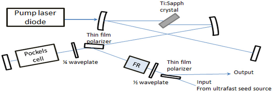
Figure 1: Typical Regenerative Amplifier Design, showing the use of a Faraday rotator (denoted FR) and its location in the system.
To achieve that goal of selecting out pulses, it is necessary to use an optic that is non-reciprocal for polarization rotation in the forward and reverse directions. An optical Faraday Rotator can accomplish the task.
Regenerative Amplifiersallow for high pulse energy, ultrashort pulses
- Multiple pass resonator design allows high gain and mJ-level energy
- Resonator design means that input and output pulses take the same beam path
Requires method to separate output pulses from input pulses
2 Polarization Selection Using a Faraday Rotator
A Faraday rotator is a passive optical device made of a magneto-optic material that has special properties. The way it operates is by rotating the plane of polarized light 45° in the forward direction and an additional 45° of non-reciprocal rotation in the reverse direction while maintaining the light’s linear polarization. When used in conjunction with polarized optics, a Faraday rotator can be used to pass light into a resonator and then send it to the output path when the polarization state has been switched. Containing low absorption, high damage-threshold optics, Coherent Faraday rotators and isolators are ideally suited for use with average power levels of up to 50W of average power for ultrafast laser systems.
When selecting a Faraday rotator, there are several criteria to keep in mind: the incident beam size, the incident optical power and energy on the rotator, and the required transmitted power for the next stage.
Find the Coherent Faraday Rotator that’s best suited for your requirements or shop online now.
3 Installing a Faraday Rotator
Installing a Faraday rotator in the optical path of a regenerative amplifier system is relatively straight forward. Each Coherent Faraday rotator comes with a User’s Manuali, which describes how to align the device in the beam path. The parameters of optical beam size, optical power and center wavelength and bandwidth must be taken into account when selecting the appropriate rotator. Our products are built to the exacting specifications of the selected model. See Figure 1 for an example of where to install a Faraday rotator in a regenerative amplifier system. An example of a real-world application can be found in reference 2ii.
4 Considerations Related to Dispersion
Dispersion is a significant issue for ultrafast lasers, one that can affect the pulse duration and therefore, the peak power, of ultrashort pulses. Dispersion occurs when light pulses travel in a medium where the phase velocity depends on its frequency (or wavelength). The material used to make a Faraday rotator is dispersive, and therefore pulses traversing through this device can broaden in length, although the magnitude and relevance of that effect depends on both the initial pulse and the application.
Generally, Ti:Sapphire regenerative amplifier systems produce pulses on the order of 20 fs or longerii, with an optical bandwidth in the range of 30 – 40 nm or more. The actual system bandwidth, along with the length of the Faraday rotator used in the system, will dictate the amount of pulse broadening that will occur when pulses traverse through the device. Other optics in the system may in fact introduce more chromatic dispersion than the Faraday rotator, and the total amount of dispersion from the chain of optics, particularly from the Pockels cell switching optic, will need to be carefully compensated.
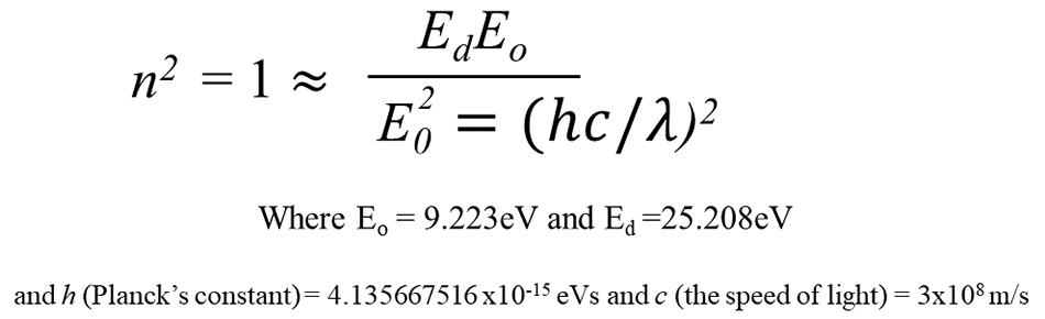
An example of how a Faraday rotator using 8 mm of Terbium Gallium Garnet (TGG) can affect the pulse duration of ~ 800 nm ultrashort pulses over the range from 10 – 10,000 fs, is shown in Figure 2. The graph was generated by determining how much group velocity dispersion (GVD) occurs for 800 nm pulses. This was done using the Sellmeier Equation for TGGiii,
The group velocity dispersion (GVD), which introduces a frequency dependent delay to the different spectral components of the pulse (typically in units of fs2/m) is expressed asiv:
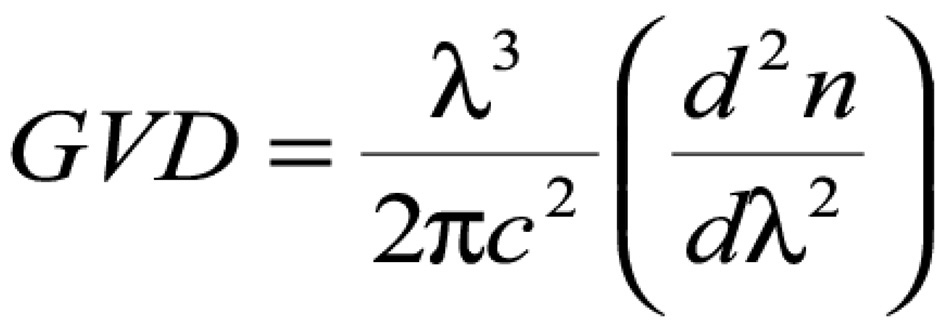
Solving analytically for the 2nd derivative of the refractive index, it is possible to calculate GVD and then the actual second order dispersion for a specific device (here denoted as β2, the second-order group delay dispersion), related to GVD by multiplying GVD by the length of the material – in this case, the TGG used in the rotator. This information can in turn be used to calculate the output pulse duration for given input pulse duration, after traveling through the length of TGG rotator material. For the case where the input pulse length squared, t0 2 , is much less than β2, an equation to express the pulse broadening proportional to β2 can be usedv.
By performing these calculations, the amount of dispersion, β2, over the range of 800 nm was found to be ~ 1500 fs2 for 8 mm long TGG. The estimated broadening from that amount of second order dispersion for pulses in the range of 10 – 10,000 fs is shown in the graph below. Note that for pulses > 75 fs, pulse broadening is not an issue. However, for many regenerative amplifier systems, the dispersion of the TGG in the Faraday rotator will have to be accounted for in the dispersion compensation scheme to achieve the shortest possible pulses.

Figure 3: Broadening of a femtosecond pulse at ~ 1050 nm after propagation through 8 mm of TGG (blue curve); the red curve shows the output for undistorted pulses.
5 Conclusions
When designing ultrafast laser systems with regenerative amplifiers, the use of a Faraday rotator is key to its operation. The use of a Coherent Faraday rotator in your laser system can help you achieve target performance.
Contact us for more information on how to use Coherent Faraday rotators in your ultrafast fiber laser systems.
References:
i Coherent User Manual for Faraday Rotators and Isolators
ii C. Barty, T. Guo, C. Le Blanc, F. Raksi, C. Rose-Petruck, J. Squier, A.Tian, K. Wilson, V.Yakovlev, and K. Yamakawa, ”Generation of 18-fs, multiterawatt pulses by regenerative pulse shaping and chirped-pulse amplification”, Opt. Lett. vol. 21, 668 (1996).
iii U. Schlarb and B. Sugg, “Refractive Index of Terbium Gallium Garnet”, Phys. Stat. Sol. (b) 182 K91 (1994)
iv As one source, see “Nonlinear Fiber Optics” by G. P. Agrawal for more details on group velocity dispersion
v. See the section on Dispersive Pulse Broadening and Chirping at: http://www.rp-photonics.com/chromatic_dispersion.html