WHITE PAPER
WHY USE QUASI-SIMULTANEOUS LASER POLYMER WELDING?
The quasi-simultaneous technique for through transmission laser welding (TTLW) delivers better results than other methods in many applications. This is especially true where part distortion must be completely avoided, or with parts having complex weld seam geometries. But getting optimum quality in a quasi-simultaneous welding process requires a high degree of process control. This is particularly necessary for maintaining a stable, consistent process which is scalable and can be replicated in multiple production lines. Accomplishing this usually involves closed-loop clamping force control followed by thermal imaging.
Polymers offer a unique set of features, including their mechanical properties, corrosion resistance, biocompatibility, and electrical and thermal insulating characteristics. Polymers also generally cost less than other materials. All this has driven their increased use in a wide variety of products.
In many instances, polymer parts must be joined during production. For higher-value products – especially medical devices and sensors used in automotive or industrial applications – this joining must be accomplished with high mechanical precision, no part distortion, minimal particulate debris production, and excellent bond strength.
Getting it together with polymers
For volume production, joining is frequently accomplished using some form of welding. Especially for the most demanding applications, laser welding has emerged as the preferred technology.
Compared to other methods, laser welding often delivers higher weld quality, strength, and precision, along with better repeatability, no particulate generation, and lower thermal and mechanical effects. But there are actually several different techniques for laser polymer welding, and each of these has a variety of specific implementations.
Most of these are forms of “through transmission laser welding” (TTLW). This method involves joining one part that is transparent at the laser wavelength to another plastic which is opaque. The two parts are placed in contact, with the clear part on top. The laser is focused in through the clear part, and down towards the opaque one. It heats and melts the opaque part causing them to be joined.
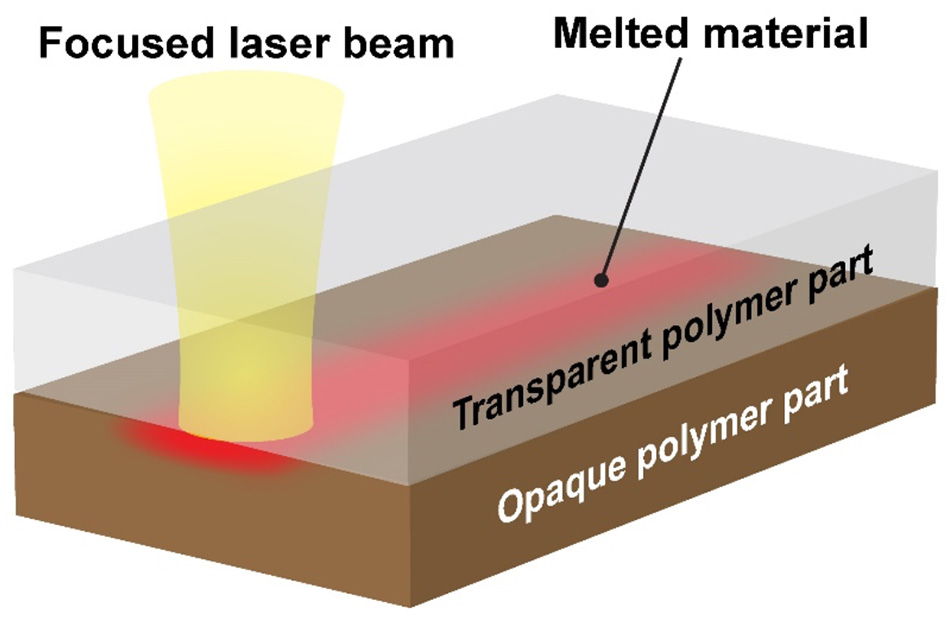
Figure 1. In TTLW, laser light passes through the transparent top part and melts the bottom one to form a bond.
The most common TTLW techniques are summarized here:
Contour: In the same manner as traditional laser welding of metal, the laser beam traces out the weld path a single time. Because of this, only a small portion of the weld path is molten at any time.
Quasi-simultaneous: In this case, the laser beam rapidly traces over the entire weld path numerous times. This is done so quickly that the entire weld seam becomes molten all at once.
Line: Here, the laser beam is formed into a thin line which is as long as the width of the part. This line is swept over the entire part surface one time. Only part of the weld path is molten at any given moment.
Simultaneous: The laser is projected in a static pattern that matches the shape of the weld seam. This causes the entire weld seam to become molten all at once.
The table summarizes the various capabilities, advantages, and disadvantages of each of these methods.
Method |
Advantages |
Disadvantages |
Typical Applications |
Contour |
No limit on part size. Can weld any shape part and produce 3D welds. Very flexible and easily changed. |
Highly localized part heating can cause distortion. |
Automotive taillights. |
Quasi-Simultaneous |
Minimal thermal stress avoids part distortion. Very flexible and easily changed. |
Maximum part size typically 400 mm x 400 mm. Limited to 2D welds. |
Precision medical devices and electronic sensors. |
Line |
Easy to implement. Compatible with relatively large parts. |
Doesn’t allow making localized changes to laser power or beam speed. Not flexible. Highly localized part heating can cause distortion. |
High volume medical component production. |
Simultaneous |
Short cycle time. Minimal thermal stress avoids part distortion. |
Extremely limited in terms of part shapes it can process. Limited to a few simple seam geometries, like lines or circles. Not at all flexible. Inhomogeneous and unstable energy distribution when using a multi-fiber configuration. |
High-volume consumable goods production. |
Quasi-simultaneous welding
Quasi-simultaneous (QS) welding is the most widely used technique for joining precision, high-value parts which have anything other than the simplest seam geometries (for example a radial weld or a circular pattern). Because it evenly heats the entire weld seam at once, QS welding delivers high-quality joints and avoids part distortion. From a practical standpoint, it’s a flexible process which can be easily altered through software control. QS welding is also a cost-effective method that is compatible with a production environment requiring short cycle times, and in which batch sizes can vary from small to large.
One important form of QS welding is the “collapse rib” method. The illustration shows the main elements of this. In this technique, the bottom part has a thin protruding rib which mates into a corresponding groove in the top part. However, the groove is a bit wider than the rib.

Figure 2. Schematic of the main steps in the “collapse rib” method of quasi-simultaneous TTLW.
The bottom rib is partially melted by the laser during welding while clamps actively press the two parts together. Molten material flows and fills some of the gap between the top and bottom parts. This then resolidifies to make the weld joint. This particular type of TTLW is especially useful because it delivers a good weld joint even if the parts aren’t perfectly flat or tightly toleranced.
QS welding process monitoring
Maximizing the benefits of QS welding, in terms of seam quality and yields, requires accurate process monitoring. For the “collapse rib” method in particular, a key element of this is “collapse control.”
“Collapse control” usually consists of active monitoring and management of the collapse height – that is, the amount that the top part moves down during welding. Specifically, automatic part collapse height measurement is used for closed-loop clamping force (and therefore speed) control, as well as to regulate laser power.
Coherent employs a more sophisticated version of “collapse control” in our polymer welding systems. This uses integrated force sensing transducers for closed-loop control of servo motor-driven clamping, rather than just height measurement. No other manufacturer employs this method. Some use the servo motor current as the feedback signal, but this doesn't deliver the same measurement accuracy and degree of dynamic control. Other manufacturers don't use servo motors at all. Instead, they use pneumatic actuators which generally don’t provide the precision or response speed necessary for optimum results.


Figure 3. QS polymer welding without (left) and with (right) high accuracy, real-time, closed-loop force control. This approach enables both collapse distance and applied force to be maintained in the center of the process window. This delivers consistent welds, even with material, dimensional, or other part-to-part variations.
This feedback allows the system to correct for part-to-part dimensional variations or inconsistencies in material absorption characteristics. It improves process consistency, even when there are changes in the ambient environment or the parts themselves – thus, it expands the process window. It also allows easy compensation for machine-to-machine differences. This enables a process developed in one location to be moved to another location and still reliably deliver the same results.
Thermal imaging
After a weld is completed, a thermal imaging (infrared) camera system can be used to assess weld quality. Thermal imaging actually measures the temperature at the surface of the top transparent part, rather than internally at the weld seam itself. However, this surface temperature data provides much more useful information about weld quality than a direct measurement of the weld seam temperature.
To understand why this is so, keep in mind that the laser only directly heats the bottom opaque part. The top transparent is melted by conduction because it is held in contact with the bottom part.
Thus, measuring the surface temperature of the top part after welding reveals two things. First, how well the bottom part absorbed laser energy and how thoroughly it was melted. Second, how consistently the clamping force was applied across the part to conduct this heat into the top part and melt it, too.
The thermal vision check delivers an image of the entire weld seam. Any breaks along the path reveal gaps in the weld seam, and variations in line thickness indicate weak spots in the weld.
Typically, thermal vision is used as a post weld quality analysis tool. It can immediately identify bad parts, allowing them to be rejected. This saves the manufacturer money because it prevents building more value into a bad part. And, of course, it prevents shipping a bad part to a customer.
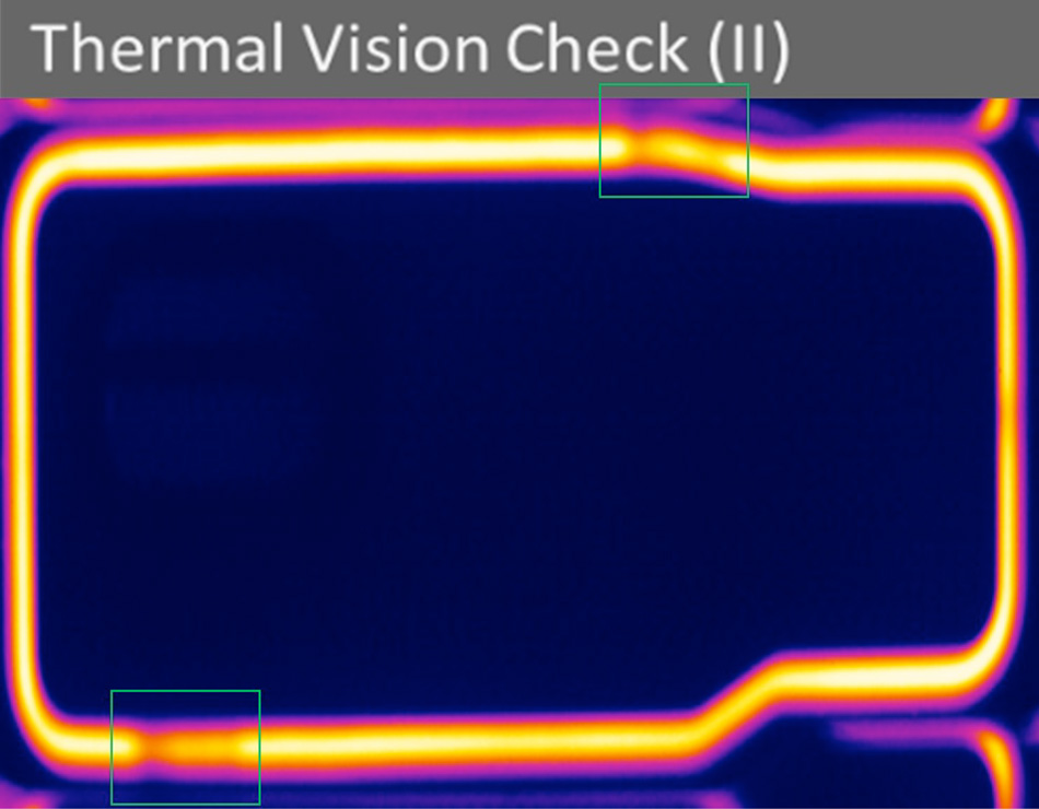
Figure 4. Real-time thermal monitoring allows weld defects (indicated in green) to be immediately identified and often corrected on the fly.
Conclusion
Quasi-simultaneous TTLW is a particularly useful method for demanding polymer joining applications. It can deliver even complex-shaped welds with high weld precision, excellent cosmetics, and good mechanical characteristics. If designed correctly, it doesn’t create any part distortion and generates no particulates, eliminating the need for any post-processing. Especially when implemented using closed-loop clamping force control and thermal monitoring, it provides a robust and reliable process that is also modular and scalable.